Pluto Rover
WBGS Young Engineers 2020
Introduction
Welcome to the documentation and refrence page for the Watford Boys Engineering Education Scheme project.
Project Overview return to top
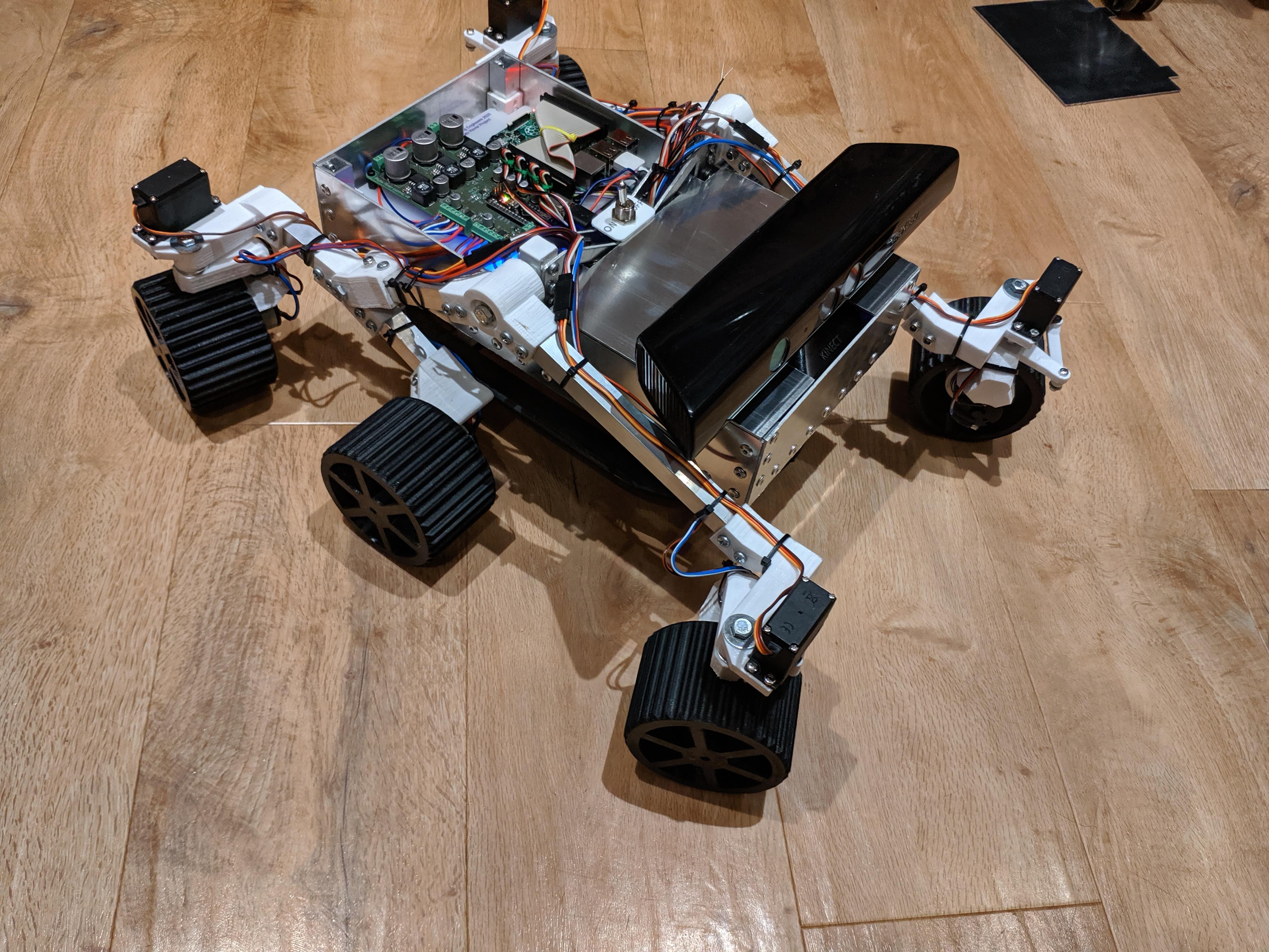
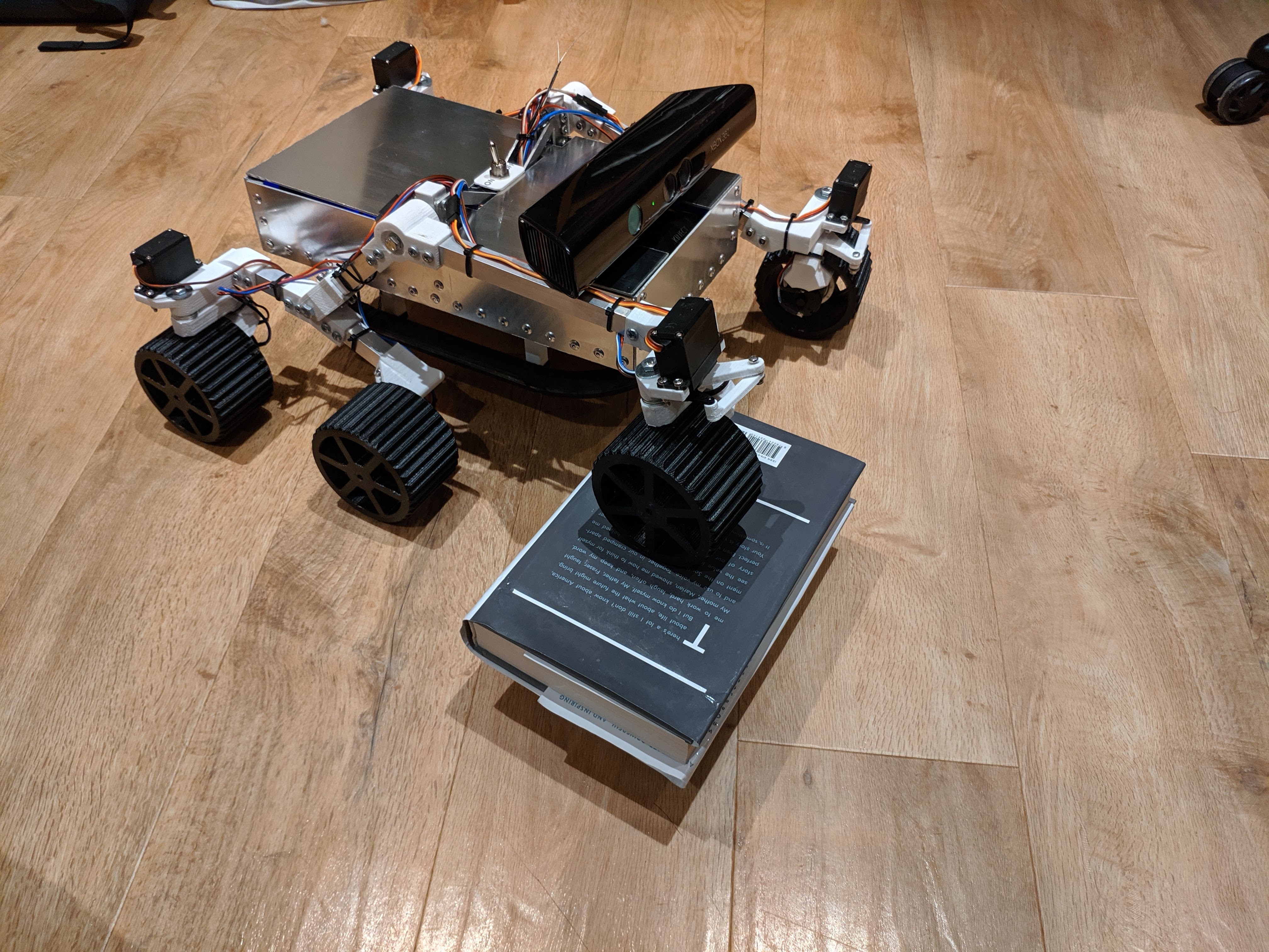
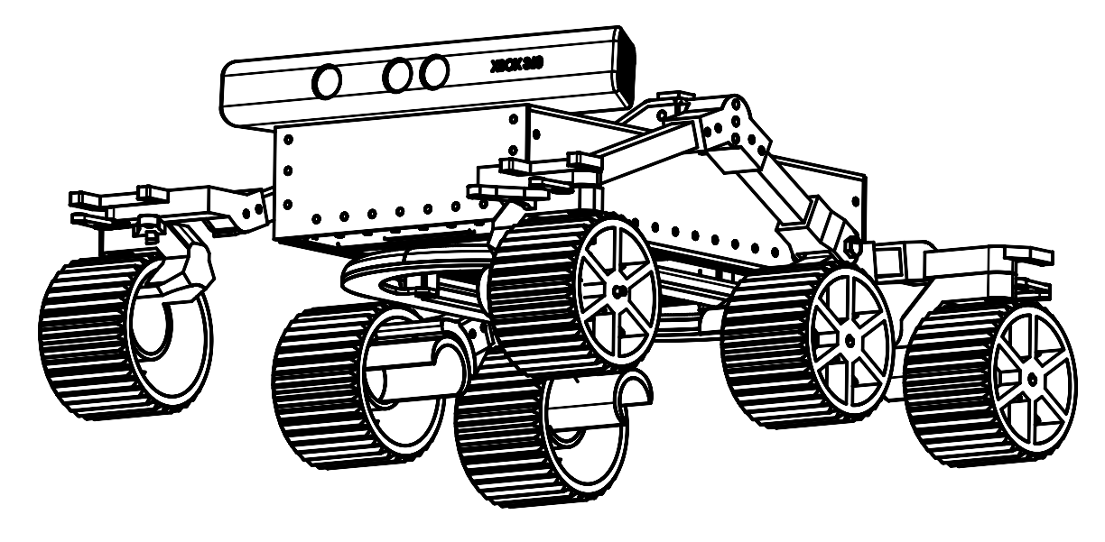
The WGBS 2020 Young Engineers team designed and constructed a Pluto Rover prototype, with the primary aim being able to traverse the terrain of Pluto and detect metals. The key requirements of the rover were to be manoeuvrable, be able to drive over rugged terrain, be able to drive autonomously (due to signals taking 4 hours 27 minutes to travel from the Earth to Pluto), and to be able to reliably detect metals. The team designed a rocker-bogie rover design to facilitate large suspension travel with limited moving parts and to allow for a 4-wheel steering system incorporating Ackermann steering angles for maximum manoeuvrability and longevity. Autonomous steering was achieved by taking the depth images from the Xbox Kinect V1 and processing them on the Raspberry Pi to generate a depth map to allow for routing decisions to then be made by the Pi. Metals are detected using a pulse induction metal detector mounted below the chassis, run off an Arduino Nano integrated on the custom PCB.
Use return to top
The rover can be controlled using its remote control. Autonomous mode is trickier to get enabled and detailed instructions are not available.
Manual demonstration
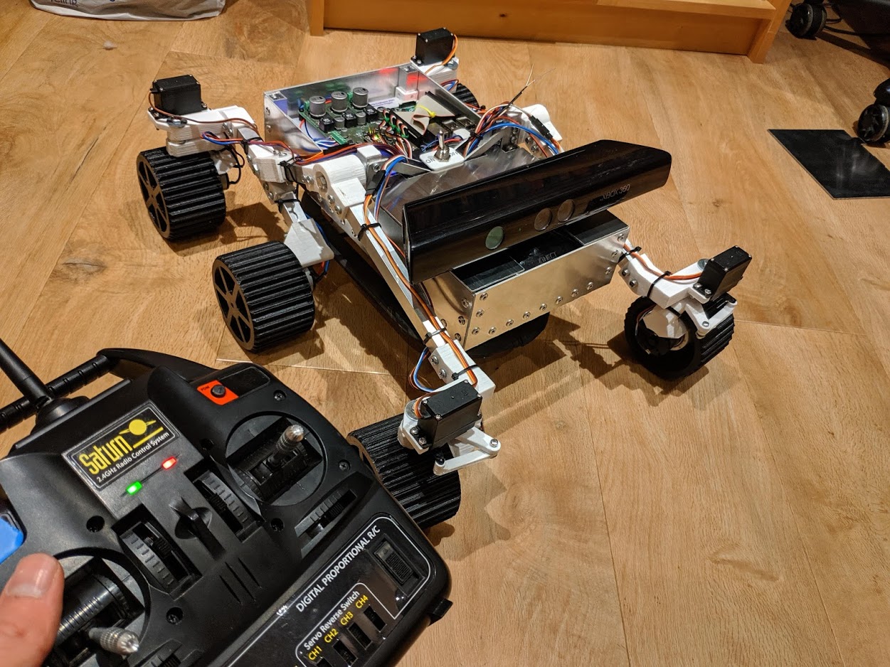
When the rover is powered on, the controller board checks to see if it can detect a signal from the remote control. If it can, the rover enters remote control mode until the power is cycled.
The left stick on the controls both throttle (forward/back) and steering (left/right).
Charging
DO NOT OVERVOLT. 24V DC is the MAXIMUM power supply voltage that can be plugged into the barrel connector.
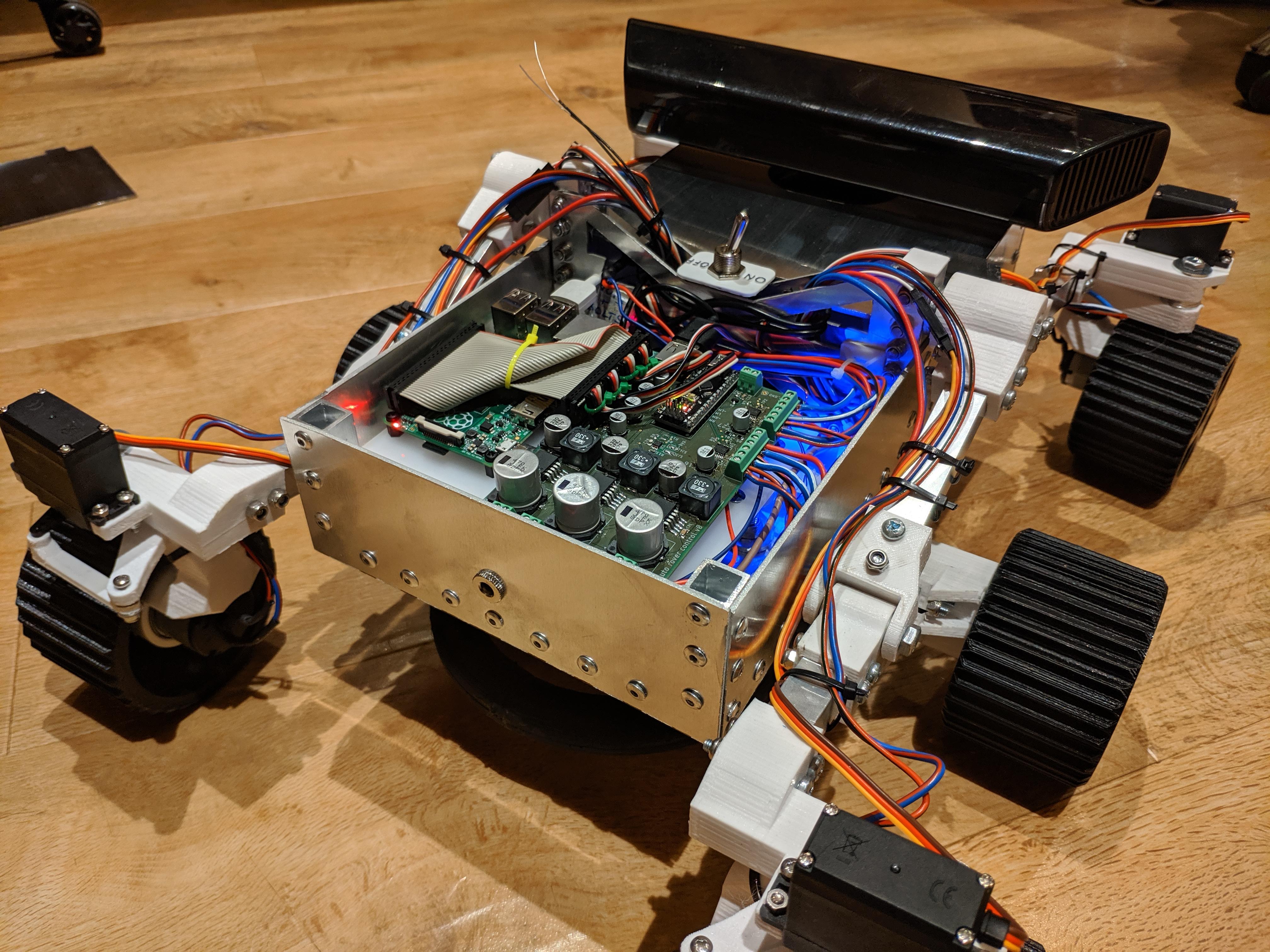
The rover is powered by 4 lithium-ion batteries mounted under the PCB. They are attached to a Battery Management System (BMS) circuit to allow for constant current charging. The system also ensures that the batteries should never be overcharged, but it is always reccomended to supervise the rover while charging.
The barrel connector on the back of the rover is wired into a buck converter which reduced the voltage for the BMS. NEVER attempted to bypass the barrel connector.
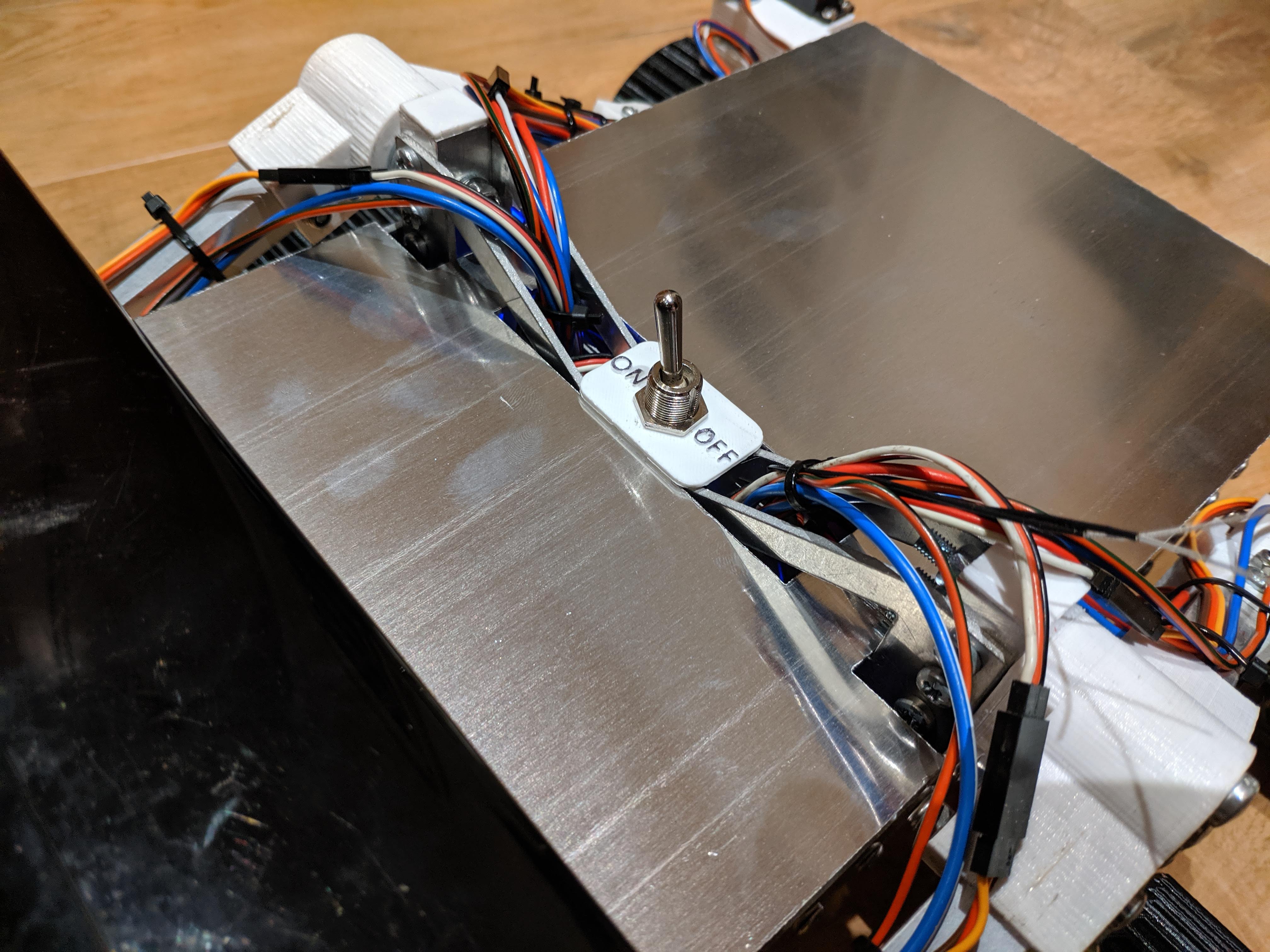
The rover can be switched on using the on/off switch located on the top of the rover.
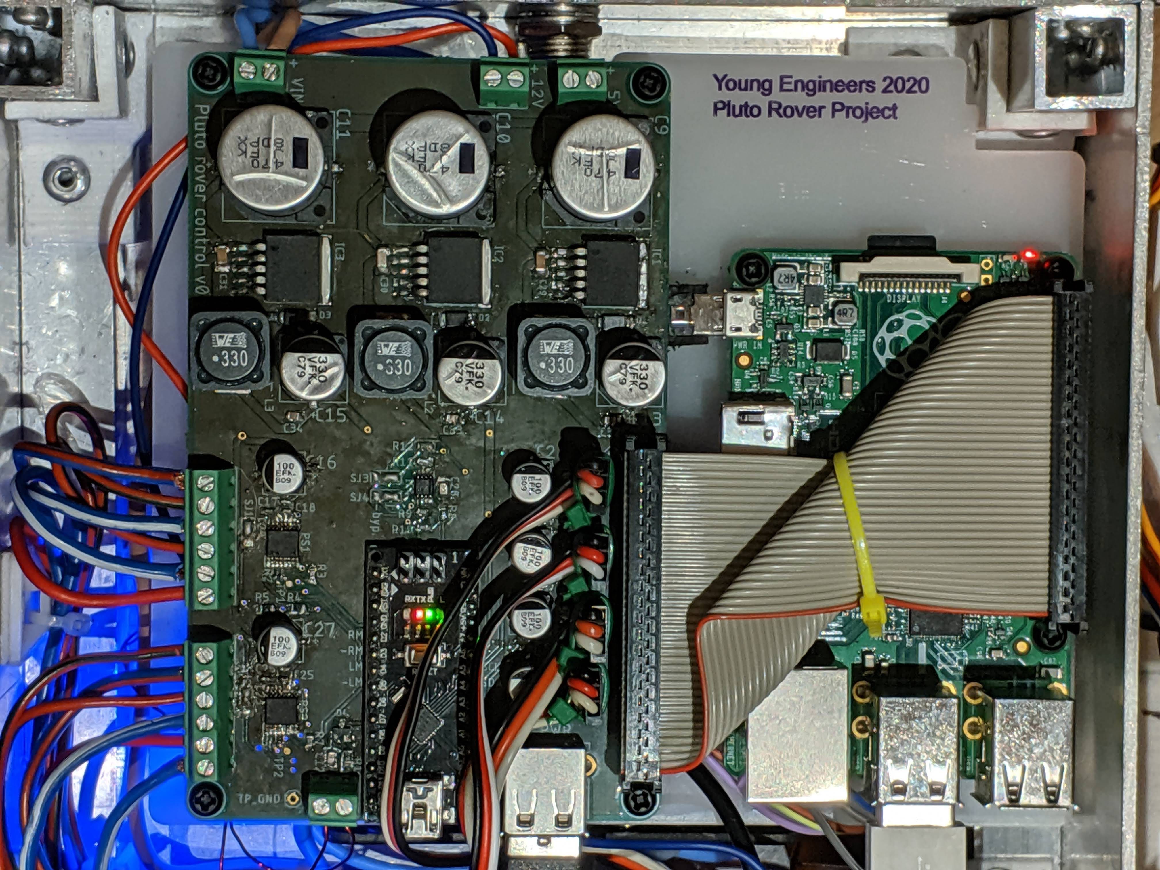
PCB return to top
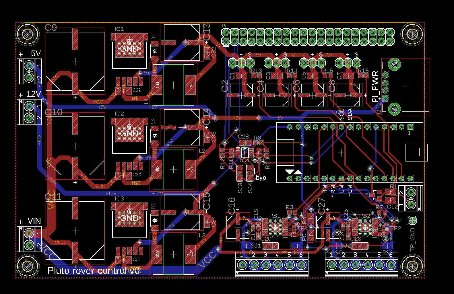
The PCB development was one of the most complex parts of the
rover project. It serves several key functions:
> Directly controlling and driving the motors
in both directions at variable speeds with two H-Bridge
circuits.
> Driving each of the servos.
> Detecting metals by measuring a relative value for
the inductance of the underside coil.
> Communicating with the Pi via I2C: sending metal
detection results and reciving automatic controls.
> Recieving controls from the manual reciever.
> Providing power to the servos, motors, Pi and
control circuitry.
For more information on the PCB design process please click here.
CAD files and drawings return to top
Mechanical model files are provided in the IGES format. PCB files are in Eagle format.
Full report return to top
Gallery return to top